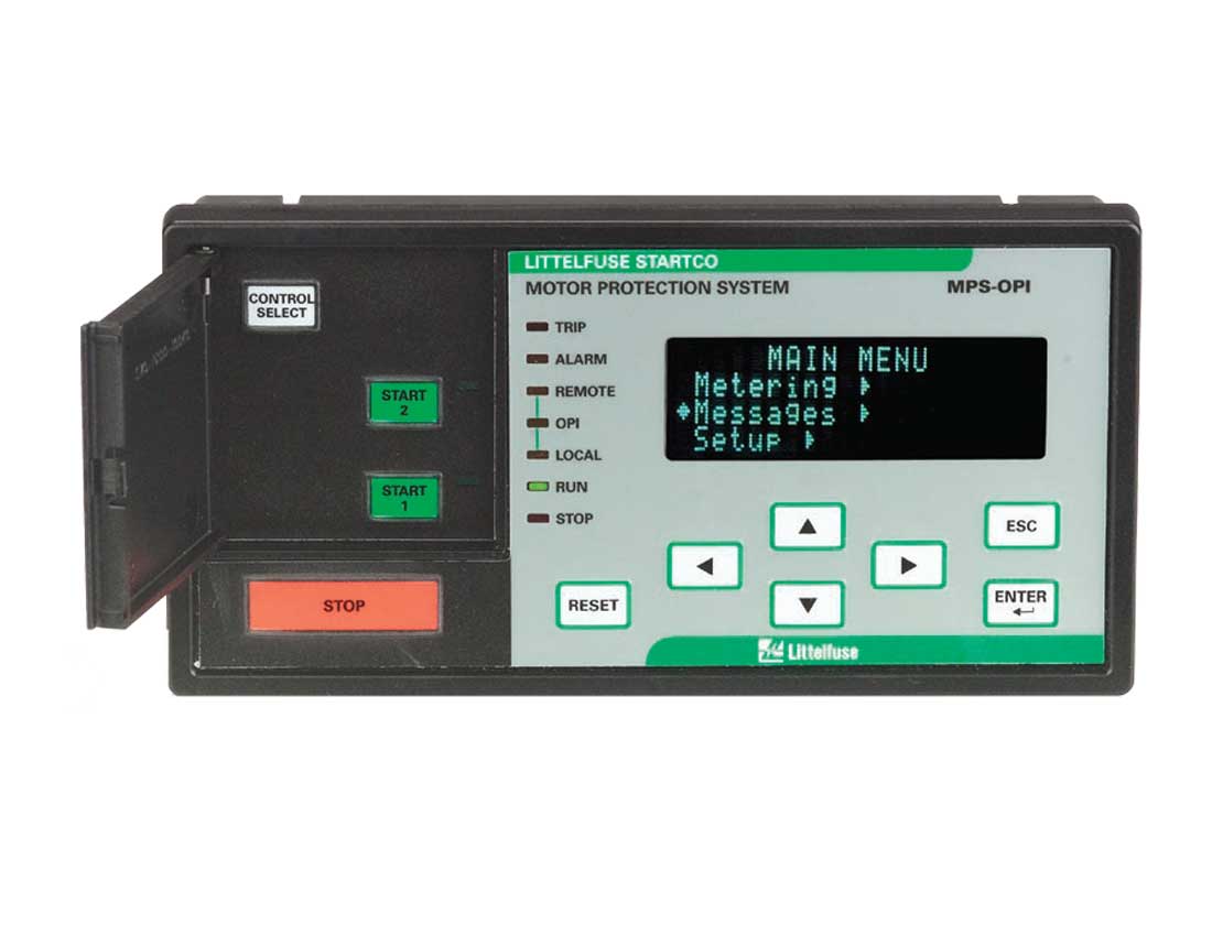
Motor Protection Relay
MPS Series
- 22 protective functions
- Reduced overcurrent mode minimizes arc flash hazards during maintenance
- Programmable inputs and outputs provide a flexible hardware platform
- Remotely view measured values, event records and reset trips
Description
The Littelfuse MPS Motor Protection System monitors voltage, current, and temperature to provide a comprehensive package of 22 motor overload protection functions.
The MPS is a modular system with integrated protection, motor control, metering, and data-logging functions. This system is typically used to provide protection for three-phase low and medium-voltage, medium to high-horsepower induction motors.
We are the exclusive NSW supplier of Littelfuse protection relays and controls for the protection, safe control and distribution of electrical power in industrial applications.
Overload – IEEE # 49, 51
Extends motor life and prevents insulation failures and fires.
Current unbalance/Phase loss/Phase reverse – IEEE # 46
Prevents overheating and extends motor life.
Overcurrent/Jam – IEEE # 50, 51
Prevents catastrophic failures and fires; extends motor life.
Undercurrent – IEEE # 37
Detects low level or no-load conditions.
Earth fault – IEEE # 50G/N, 51G/N
Prevents catastrophic failures and fires.
RTD temperature – IEEE # 38, 49
Optional MPS-RTD module for high-ambient or loss-of-ventilation protection.
Overvoltage – IEEE # 59
Prevents stress to insulation.
Undervoltage – IEEE # 27
Prevents a start attempt when it will damage the motor.
Voltage unbalance – IEEE # 47
Detects unhealthy supply voltage.
Phase differential – IEEE # 87
Provides sensitive protection for high-resistance winding faults.
Dynamic thermal mode
Provides protection through starting, running, overload, and cooling cycles.
Reduced overcurrent mode
Minimises Arc-Flash hazards during maintenance.
Starter control
Simplifies the installation by reducing component count.
Metering
Displays the measured and calculated motor parameters.
Data logging
On-board 64-event recorder helps with system diagnosis.
Data Sheet and Manuals
MPS Data SheetMPS ManualMPS DeviceNet ManualFPS MPS Profibus ManualMPS Profibus Manual MPS v1 90 and lowerMPS Modbus TCP and Ethernet IP Interface
CAD Drawings and Models
MPS OPI CAD DrawingMPS-RTD CAD DrawingFPS MPS RTD CAD DrawingMPS Block CAD DrawingMPS CTU CAD Drawing
Software and Manuals
SE-Comm-RIS v4.2 SoftwareMPS FPS Firmware Update Instruction
Protective Functions (IEEE Device Numbers)
Overload (49, 51), RTD temperature (38, 49), Phase reverse (current) (46), Unbalance (current) (47), Overfrequency (81), Underspeed (14), Overcurrent (50, 51), Starts per hour (66), Jam, Phase loss (current) (46), Undercurrent (37), Undervoltage (27), Unbalance (voltage) (47), Phase reverse (voltage) (47), Failure to accelerate, Power factor (55)
Input Voltage
65-265 Vac, 25 VA; 80-275 Vdc, 25 W
Power-Up Time
800 ms at 120 Vac
Ride-Through Time
100 ms minimum
24-Vdc Source
100 mA maximum
AC Measurements
True RMS and DFT, Peak, 16 samples/cycle, and positive and negative sequence of fundamental
Frequency
50, 60 Hz or ASD
Inputs
Phase current, Earth-leakage current, Phase voltage, 7 digital, tachometer, 1 analog
Output Contacts
5 contacts - see manual
Communications
Allen-Bradley, DFI and Modbus RTU (Standard); DeviceNet, Profibus, Ethernet (Optional)
Conformally Coated
Standard feature
Warranty
10 years
Mounting (Control Unit)
Surface
Mounting (Current Input Module)
Panel, Control-Unit mounted